Kinematic roll centre analysis of the Acura RSX rear suspension
This article is part of a series on the kinematic simulation and analysis of the Acura RSX suspension. To learn more, feel free to check my other posts:
Front Suspension
- Analysis of the Acura RSX front suspension geometry
- Kinematic curves of the Acura RSX front suspension
- Motion ratio curves of the Acura RSX front suspension
- Kinematic roll centre analysis of the Acura RSX front suspension
Rear Suspension
- Kinematic curves of the Acura RSX rear suspension
- Motion ratio curves of the Acura RSX rear suspension
- You are here! - Kinematic roll centre analysis of the Acura RSX rear suspension
Full Vehicle
Modern vehicle suspension systems are carefully designed to react handling loads while maintaining good ride and comfort. Performance objectives are often at odds with chassis packaging where cabin space takes precedence over suspension packaging. For performance enthusiasts hoping to operate the car at its limits, it means dealing with compromises from the factory.
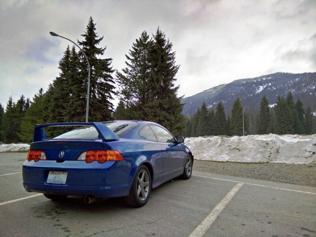
The Acura RSX is an example of a car that has this challenge. As a daily driver, its compact rear suspension makes it a very practical car. From a performance perspective, the tradeoffs to achieve this are less clear. To answer this, we ran a series of kinematic studies.
In this article, we will be analyzing the kinematic roll-centre of the Acura RSX rear suspension in pure heave and roll.
Suspension Design
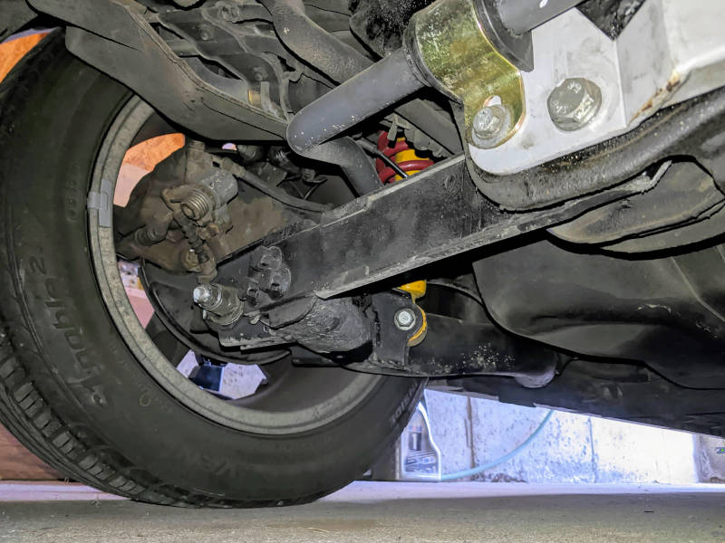
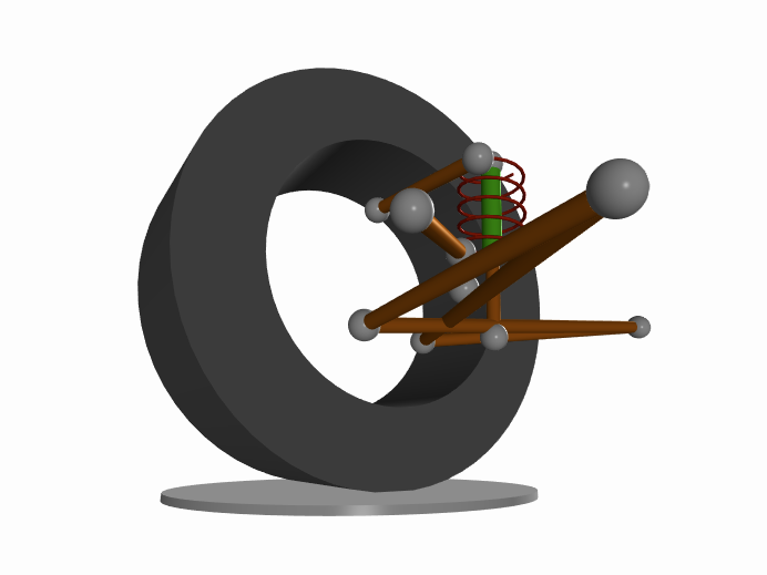
The Acura RSX rear suspension features an H-arm and camber link. The H-arm is formed by the lower control arm and is responsible for reacting braking and cornering forces. The camber link forms the upper control arm and reacts only cornering forces. Both lower and upper control arms locate the front-view kinematic roll centre. The side-view kinematic instant centre is controlled solely by the lower control arm. The rear suspension is pictured below with the real life and virtual representations shown on the left and right respectively.
This suspension topology is cost effective with minimal compromise on kinematic performance. Its compact size and reduced chassis attachment points contribute to its cost effectiveness. Aftermarket adjustment to the geometry is limited since the lower control arm has the responsibility of four links. Practically any major change to the suspension geometry would require a completely new knuckle or lower control arm. Fortunately, we can analyze the design to determine how to make the most of it without resorting to modification.
Kinematic Roll Centre
The kinematic roll centre is a virtual point on the axle plane where cornering forces can be resolved into the suspended mass.
The determination of the front-view kinematic instant centres is simplified by assuming that all four lower control arm points lie on a plane. This means that the front-view kinematic instant centre is found at the intersection of:
- the plane formed by the H-arm
- the line formed by the camber link projected onto the axle plane
- the axle plane defined by the contact patches and the wheel centres
The intersection of the lines formed by the front-view kinematic instant centre and the tire contact patch is the kinematic roll centre.
It is important to note that we are using kinematic constructs to make assumptions about how forces are reacted into the suspended mass. This distinction is important because they do not translate directly. For this reason, we explicitly call this point the kinematic roll centre.
Parallel Wheel Travel
Moving the suspension in parallel wheel travel helps us understand what happens to the kinematic roll centre when both wheels are displaced together. Since these cars are often lowered with the installation of aftermarket coilover kits, this gives us an idea of how much the geometry deviates from factory trim.
A nice property you can already see from the animation is that the kinematic roll centre stays above the ground for the entire suspension travel. This is confirmed in the simulation results.

The kinematic roll centre is nominally 168 mm above the ground at factory ride height. You can expect the kinematic roll centre to change at a rate of 1.07 mm per mm of heave at factory ride height.
Opposite Wheel Travel
Opposite wheel travel is a motion where both wheels are displaced the same amount but in opposite directions. This is a considered a contrived motion because in reality the car is free to move in both heave and roll. The asymmetry created by this motion is interesting for advanced analysis.
From the animation, you can see very little movement in the kinematic roll centre. This is a fascinating property. It suggests a deliberate attempt to minimize the kinematic roll centre lateral migration. Lets take a closer look at the results from the analysis.

The kinematic roll centre height is very well controlled. We can see the kinematic roll centre height increase just over 10 mm with 4 degrees of roll.

The same can be said about the kinematic roll centre lateral migration. When measured from the vehicle centre plane, the lateral migration is only about 8mm. This is a very unique property since the kinematically induced asymmetry is kept to a minimum. The lateral position of the kinematic roll centre migrates at a rate of 1.44 mm per deg of roll when the roll angle is zero.
Final Comments
Our analysis of the Acura RSX rear suspension shows a deliberate attempt by Honda to locate the kinematic roll centre. The kinematic roll centre stays above the ground throughout the range of travel meaning that geometry correction for lowered vehicles is not necessary; you can make the chassis work with a lowered suspension kit. At nominal ride height, the kinematic roll centre lateral migration is well controlled. This is an unusual aspect to consider for most builders, but a unique one nonetheless.
By analyzing the suspension using kinematic simulation, we can start to appreciate how loads might be reacted by the suspension system. By taking an analytical approach, we can make an educated guess of Honda’s high level design objectives. For anyone serious about chassis setup, it is a huge information advantage!
Acknowledgements
This work is made possible with help from Ping Zhang at Formula Delta who shared the suspension points for the Acura RSX. You can learn more about Ping and his time attack project on his website, Facebook or Instagram.
References
- Dixon, John C. Tires, Suspension and Handling, Second Edition. Warrendale, PA: SAE International, 1996.
- Milliken, William F., and Douglas L. Milliken. Race car vehicle dynamics. Vol. 400. Warrendale: Society of Automotive Engineers, 1995.
- Blundell, Michael, and Damian Harty. Multibody systems approach to vehicle dynamics. Elsevier, 2004.