Simplified steady-state lateral load transfer analysis for spring rate and anti-roll bar selection
Handling modifications are synonymous with upgraded coilovers and anti-roll bars. Replacing them with aftermarket versions do not guarantee the vehicle will be improved. Depending the objectives, the vehicle can be adjusted to accommodate the needs of the driver. This requires tuning to achieve the desired outcome.
While many factors contribute to the vehicle directional control, the choice of spring rate and anti-roll bar size will have a big effect on the vehicle handling characteristics. This controls the lateral load transfer distribution and will affect how the tire vertical load transfer is distributed between the four corners of the car.
Lateral load transfer analysis is useful because it provides an order-of-magnitude indication of how the vehicle balance might change. We present a set of simplified equations to model the lateral load transfer based on classical techniques. To demonstrate the applicability of this analysis, we use kinematic data from the Acura RSX to compute handling metrics before and after a setup change.
Bringing balance to the vertical forces
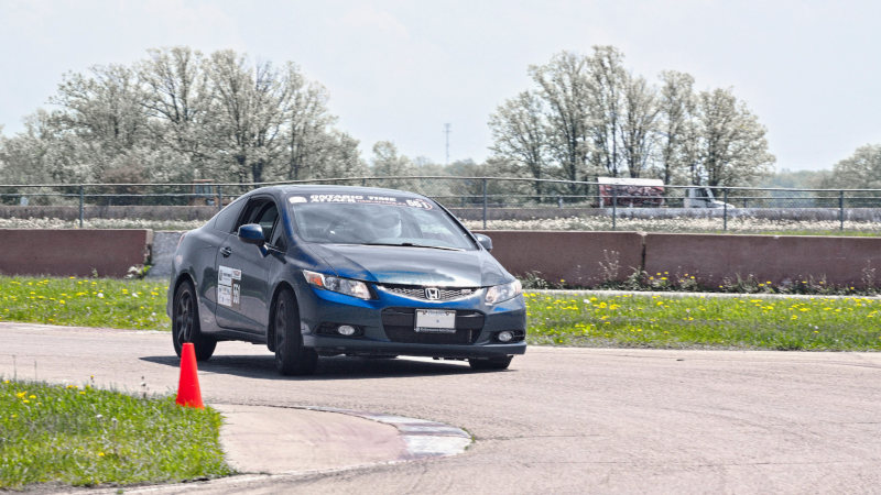
In an ideal analysis, vehicle balance would be characterized by studying the yawing and lateral dynamics directly. Several techniques exist, including the on-centre handling study of the #551 2012 Honda Civic Si we performed in 2018. Tire force and moment data is often required for such analysis and is unlikely to be available to individual analysts.
In the absence of a complete vehicle model, we must consider alternative mechanisms that are known to be correlated with vehicle handling. The lateral load transfer distribution is a metric commonly used to quantify the handling balance of a vehicle. Closely related is the roll stiffness distribution which can also be used as a metric for handling balance.
Pneumatic tires are assumed to be load sensitive meaning that the peak coefficient of friction is reduced with vertical load. Therefore, lateral load transfer decreases the total lateral force that can be generated by the tires. Modifying the vehicle with springs, anti-roll bars or geometry controls how the load transfer is distributed between the front and rear axles, thereby changing the vehicle handling balance.
Lateral load transfer
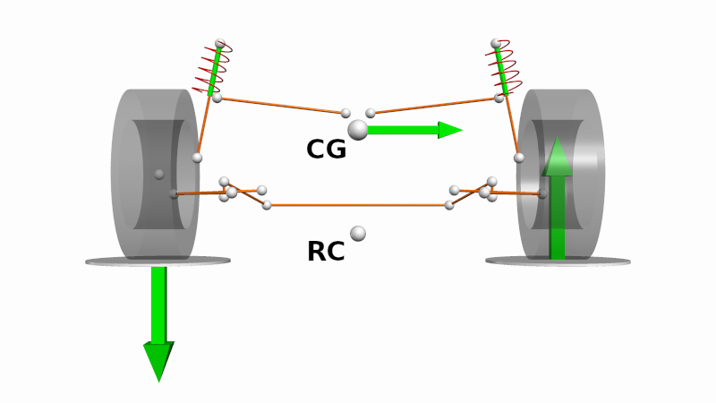
Lateral load transfer is a physical phenomenon that causes the tire vertical load on each wheel to change as a lateral force is applied to the vehicle centre of gravity. Simply put, it is the change in tire vertical load when the vehicle is cornering.
In this section, we will show the equations to compute a lateral load transfer distribution (LLTD). Astute readers will recognize that these equations are highly simplified. This is intentional. Our purpose is to obtain an order-of-magnitude indicator of the change in vehicle balance. We favour relative correlation over absolute correlation.
For more mathematically focused formulations, consider additional reading from texts such as Jazar or Pacejka.
Model assumptions
The lateral load transfer model follows a series of assumptions to simplify the analysis. The initial assumption is that the vehicle is symmetrical and is analyzed while on-centre. This means that:
- The neutral roll axis lies on the vehicle centre plane
- The vehicle centre of gravity lies on the vehicle centre plane
- The tire lateral forces are equally split between the left and right wheels
This assumption eliminates jacking forces from appearing in the analysis.
To reduce the amount of data needed with respect to the vehicle mass properties, we assume that the total vehicle mass can be substituted for the chassis mass. This means that:
- The suspended mass centre of gravity is in the same position as the vehicle centre of gravity
- The unsprung mass is negligible in comparison to the suspended mass
- The tire vertical stiffness is negligible
With regards to the model, the following simplifying assumptions are made:
- The load transfer can be analyzed at each axle independently
- The lateral acceleration experienced at each axle is the same
These assumptions allow the model simplify into a pair of two-dimensional statics problems that are trivial to solve.
In a rigid body
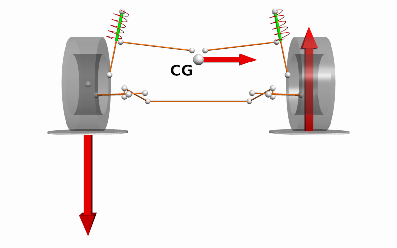
The simplest case for studying lateral load transfer is a rigid body. In steady-state, the sum of the roll moments must equal to zero. Tire vertical forces are developed at the tire contact patches when a lateral force is applied at the vehicle centre of gravity. The magnitude of the change in tire vertical load is given by the following:
\[|\Delta F_z| = \frac{mh_{CG}}{t} a_y\]Where:
- \(\Delta F_z\) is the overall change in tire vertical load [\(N\)]
- \(m\) is the overall mass of the vehicle [\(kg\)]
- \(a_y\) is the lateral acceleration experienced at the vehicle centre of gravity [\(m/s^2\)]
- \(h_{CG}\) is the centre of gravity height above the ground [\(m\)]
- \(t\) is the vehicle average track [\(m\)]
Note that the roll centre and roll stiffness do not appear in this relationship. The total magnitude of load transfer cannot be changed by adjusting suspension components; however, the distribution of this load transfer can be controlled through the suspension elements.
Roll centres and link loads
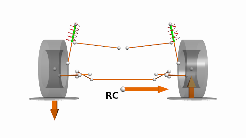
The roll centre is a point on the axle plane in which forces can be resolved into the suspended mass. In the symmetrical case, forces resolve into the roll centre without creating a roll moment about the suspended mass. Thus, an equivalent lateral force originating the tire contact patches could be a lateral force of equivalent magnitude applied at the roll centre plus a roll moment that is reacted through the suspension links. We call this the link load transfer. It is also commonly called the inelastic load transfer, or the geometric load transfer.
\[|\Delta F_{z,g,f}| = \frac{m_fh_{RC,f}}{t_f} a_y\] \[|\Delta F_{z,g,r}| = \frac{m_rh_{RC,r}}{t_r} a_y\]Where:
- \(\Delta F_{z,g,i}\) is the change in tire vertical load for axle \(i\) due to link load transfer effects [\(N\)]
- \(m_i\) is the equivalent mass of axle \(i\) [\(kg\)]
- \(h_{RC,i}\) is the height of the roll centre above the ground for axle \(i\) [\(m\)]
- \(t_i\) is the track width for axle \(i\) [\(m\)]
Roll stiffnesses
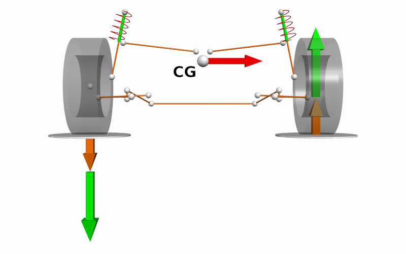
The forces acting into the suspended mass through the roll centre generates a roll moment about the suspended mass centre of gravity. This can equivalently be thought of as a lateral force applied at the suspended mass centre of gravity plus a roll moment generated by the distance between the roll centre and suspended mass centre of gravity. Beginning with a roll moment equilibrium:
\[(k_{\phi,f} + k_{\phi,r}) \phi = a_y\Big(m_f(h_{CG} - h_{RC,f}) + m_r(h_{CG} - h_{RC,r})\Big)\] \[\phi = \frac{m_f(h_{CG} - h_{RC,f}) + m_r(h_{CG} - h_{RC,r})}{k_{\phi,f} + k_{\phi,r}} a_y\]Where:
- \(\phi\) is the roll angle of the suspended mass [\(rad\)]
- \(k_{\phi, i}\) is the equivalent roll stiffness of axle \(i\) [\(Nm/rad\)]
- \(g\) is the acceleration due to earth’s gravity [\(m/s^2\)]
The change in tire vertical load due to the roll moment reacted through the springs is simply the roll angle multiplied by the roll stiffness divided by the track width.
\[|\Delta F_{z,e,f}| = \frac{k_{\phi,f}}{k_{\phi,f} + k_{\phi,r}}\Bigg[\frac{m_f(h_{CG} - h_{RC,f}) + m_r(h_{CG} - h_{RC,r})}{t_f}\Bigg] a_y\] \[|\Delta F_{z,e,r}| = \frac{k_{\phi,r}}{k_{\phi,f} + k_{\phi,r}}\Bigg[\frac{m_f(h_{CG} - h_{RC,f}) + m_r(h_{CG} - h_{RC,r})}{t_r}\Bigg] a_y\]Where:
- \(\Delta F_{z,e,i}\) is the change in tire vertical load due to the roll stiffness load transfer for axle \(i\) [\(N\)]
This component of tire vertical load transfer is called the roll stiffness load transfer. It is also commonly called the elastic load transfer.
Total load transfer
The total lateral load transfer experienced by each axle is the sum of the link load transfer and the roll stiffness load transfer.
\[|\Delta F_{z,f}| = \frac{m_fh_{RC,f}}{t_f} a_y + \frac{k_{\phi,f}}{k_{\phi,f} + k_{\phi,r}}\Bigg[\frac{m_f(h_{CG} - h_{RC,f}) + m_r(h_{CG} - h_{RC,r})}{t_f}\Bigg] a_y\] \[|\Delta F_{z,r}| = \frac{m_fh_{RC,r}}{t_r} a_y + \frac{k_{\phi,r}}{k_{\phi,f} + k_{\phi,r}}\Bigg[\frac{m_f(h_{CG} - h_{RC,f}) + m_r(h_{CG} - h_{RC,r})}{t_r}\Bigg] a_y\]Differentiating the change in tire vertical load with respect to the lateral acceleration gives us the lateral load transfer sensitivity. This is the incremental change in the tire vertical load per unit lateral acceleration.
\[\frac{d|\Delta F_{z,f}|}{da_y} = \frac{m_fh_{RC,f}}{t_f} + \frac{k_{\phi,f}}{k_{\phi,f} + k_{\phi,r}}\Bigg[\frac{m_f(h_{CG} - h_{RC,f}) + m_r(h_{CG} - h_{RC,r})}{t_f}\Bigg]\] \[\frac{d|\Delta F_{z,r}|}{da_y} = \frac{m_fh_{RC,r}}{t_r} + \frac{k_{\phi,r}}{k_{\phi,f} + k_{\phi,r}}\Bigg[\frac{m_f(h_{CG} - h_{RC,f}) + m_r(h_{CG} - h_{RC,r})}{t_r}\Bigg]\]Lateral load transfer distribution
The lateral load transfer distribution is the ratio between the axle lateral load transfer sensitivity and the total vehicle lateral load transfer sensitivity.
\[LLTD_f = \frac{\frac{d|\Delta F_{z,f}|}{da_y}}{\frac{d|\Delta F_{z,f}|}{da_y}+\frac{d|\Delta F_{z,r}|}{da_y}}\] \[LLTD_r = \frac{\frac{d|\Delta F_{z,r}|}{da_y}}{\frac{d|\Delta F_{z,f}|}{da_y}+\frac{d|\Delta F_{z,r}|}{da_y}}\]Roll stiffness distribution
In the absence of kinematic data, the link load transfer component may be omitted to obtain the roll stiffness distribution (RSD).
\[RSD_f = \frac{k_{\phi,f}}{k_{\phi,f} + k_{\phi,r}}\] \[RSD_r = \frac{k_{\phi,r}}{k_{\phi,f} + k_{\phi,r}}\]Note that the values of \(k_\phi\) are roll stiffnesses which include the effect of elastic elements and their motion ratios, and the track width.
Case Study
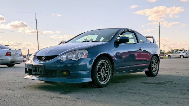
To demonstrate the applicability of load transfer modelling, we will compute the lateral load transfer distribution for the 2002 Acura RSX. Using kinematic data generated from our analysis of the Acura RSX suspension, we can compute the lateral load transfer distribution before and after a setup change to ascertain its effect.
Target vehicle
We will analyze the Acura RSX in two configurations: stock and modified. The stock configuration is a baseline that represents the design intent of the manufacturer. The modified configuration represents a vehicle with mild bolt-on performance parts. These parts do not change the underlying suspension geometry and do not interfere with the roadworthiness of the vehicle. The parameters for each configuration are shown below.
| Parameter | Stock | Modified |
|---|---|---|
| Mass [kg] | 1288 | 1288 |
| Front weight distribution [%] | 61 | 61 |
| Track, front [mm] | 1482 | 1482 |
| Track, rear [mm] | 1481 | 1481 |
| Spring rate, front [N/mm] | 48.9 | 65.7 |
| Spring rate, rear [N/mm] | 80.2 | 113.8 |
| Spring motion ratio, front [mm/mm] | 0.92 | 0.96 |
| Spring motion ratio, rear [mm/mm] | 0.59 | 0.56 |
| Sway bar effective length, front [mm] | 1008 | 1008 |
| Sway bar effective length, rear [mm] | 1026 | 1026 |
| Sway bar diameter, front [mm] | 23 | 23 |
| Sway bar diameter, rear [mm] | 19 | 24 |
| Sway bar wall thickness, front [mm] | N/A | N/A |
| Sway bar wall thickness, rear [mm] | N/A | N/A |
| Sway bar, shear modulus [GPa] | 80 | 80 |
| Sway bar motion ratio, front [deg/mm] | 0.096 | 0.096 |
| Sway bar motion ratio, rear [deg/mm] | 0.201 | 0.184 |
| Height, centre of gravity [mm] | 533 | 480 |
| Height, roll centre, front [mm] | 96 | -64 |
| Height, roll centre, rear [mm] | 168 | 120 |
| Height, ride reference, front [mm] | 223 | 173 |
| Height, ride reference, rear [mm] | 240 | 181 |
Compute the roll stiffness
For Acura RSX suspension, there are two elastic elements that contribute to the roll stiffness: the corner springs and the anti-roll bar. Assuming that the vehicle acts in pure roll, the roll stiffness contribution by the corner springs can be computed using the following.
\[k_{\phi,cs,f} = \frac{1}{2} k_{cs,f} \textrm{MR}_{cs,f}^2 t_f^2\] \[k_{\phi,cs,r} = \frac{1}{2} k_{cs,r} \textrm{MR}_{cs,r}^2 t_r^2\]Where:
- \(k_{\phi,cs,i}\) is the roll stiffness contribution from the corner springs on axle \(i\) [\(Nm/rad\)]
- \(k_{cs,i}\) is the linear spring stiffness of the corner spring on axle \(i\) [\(N/m\)]
- \(\textrm{MR}_{cs,i}\) is the motion ratio between the corner spring and the wheel centre displacement on axle \(i\) [\(m/m\)]
The anti-roll bar is assumed to be a solid, straight cylindrical bar connecting the left and right wheels over an effective length. The resistive roll moment is provided by its torsional stiffness. Assuming that the vehicle acts in pure roll, the roll stiffness contribution by the anti-roll bar can be estimated using the bar dimensions and material properties.
\[k_{\theta,arb,f} = \frac{\pi D_f^4G}{32l_f}\] \[k_{\theta,arb,r} = \frac{\pi D_r^4G}{32l_r}\] \[k_{\phi,arb,f} = k_{\theta,arb,f} \textrm{MR}_{arb,f}^2 t_f^2\] \[k_{\phi,arb,r} = k_{\theta,arb,r} \textrm{MR}_{arb,r}^2 t_r^2\]Where:
- \(k_{\theta,arb,i}\) is the torsional stiffness of the anti-roll bar on axle \(i\) [\(Nm/rad\)]
- \(k_{\phi,arb,i}\) is the roll stiffness contribution from the anti-roll bar on axle \(i\) [\(Nm/rad\)]
- \(D_i\) is the anti-roll bar diameter on axle \(i\) [\(m\)]
- \(l_i\) is the effective anti-roll bar length on axle \(i\) [\(m\)]
- \(G\) is the shear modulus of bar material [\(Pa\)]
- \(\textrm{MR}_{arb,i}\) is the anti-roll bar motion ratio between the twist angle of the anti-roll bar and the wheel centre displacement on axle \(i\) [\(rad/m\)]
The corner springs and the anti-roll bar are configured in parallel, meaning that the roll stiffness per axle is simply the summation of the two stiffnesses.
\[k_{\phi,f} = k_{\phi,cs,f} + k_{\phi,arb,f}\] \[k_{\phi,r} = k_{\phi,cs,r} + k_{\phi,arb,r}\]Where:
- \(k_{\phi,i}\) is the roll stiffness of axle \(i\) [\(Nm/rad\)]
The following values for the roll stiffness are computed for the vehicle under study.
| Parameter | Stock | Modified |
|---|---|---|
| Roll stiffness, front [Nm/deg] | 1027 | 1395 |
| Roll stiffness, rear [Nm/deg] | 1004 | 1686 |
| Roll stiffness [Nm/deg] | 2031 | 3081 |
Results
With all input quantities known, they can be substituted into the load transfer equations. The lateral load transfer distribution and other metrics are summarized in the table below. Additional metrics have been included to highlight how the fidelity of the model will affect the results.
| Metric | Stock | Modified | Delta (±/%) |
|---|---|---|---|
| Weight distribution [%] | 61 | 61 | - |
| Spring rate distribution, rear [%] | 62.1 | 63.4 | +1.3 (+2.1%) |
| Wheel rate distribution, rear [%] | 40.3 | 37.1 | -3.2 (-7.9%) |
| Roll stiffness distribution, rear [%] | 49.4 | 54.7 | +5.3 (+10.7%) |
| Lateral load transfer distribution, rear [%] | 50.2 | 63.6 | +13.4 (+26.7%) |
In the modified configuration, the lateral load transfer distribution moves rearward +13.4%. This is a 26.7% relative increase compared to the stock configuration. Our subjective on-track evaluation suggests the modified configuration has a very aggressive handling balance. This observation is correlated with change in the lateral load transfer distribution.
The roll stiffness distribution does not capture the effect of the roll centre. While the directionality of the metric is correct, it suggests a change that is about half the magnitude suggested by the lateral load transfer distribution.
The spring rate and wheel rate distributions are limited to vertical dynamics only, so the effect of the increased rear anti-roll bar diameter is not captured. Interestingly, it seems as if the corner spring rates were deliberately chosen in the modified configuration to maintain the vertical stiffness distribution.
Final comments
Vehicle analysis and handling metrics are indispensible tools for chassis setup. In this analysis, we computed the lateral load transfer distribution and the roll stiffness distribution. These metrics are highly correlated with vehicle balance and can be used to ascertain the effect of new springs and anti-roll bars on vehicle handling.
Vehicle understanding is an important aspect to success. By understanding the underlying mechanisms of vehicle performance, we can have confidence in our setup decisions. Performance and cost are not mutually exclusive. Using a systems approach, we can determine the most efficient pathway to success and maximize the “bang-for-your-buck” of your project build. This is just one of the tools we use at Formula Delta to achieve this.
References
- Dixon, John C. 1996. Tires, Suspension and Handling, Second Edition. Warrendale, PA: SAE International.
- Milliken, William F., and Douglas L. Milliken. Race car vehicle dynamics. Vol. 400. Warrendale: Society of Automotive Engineers, 1995.
- Jazar, Reza N. Vehicle Dynamics: Theory and Application. 2008.
- Pacejka, Hans. Tire and Vehicle Dynamics. Elsevier, 2012.
- Shigley, Joseph E. Mechanical Engineering Design. McGraw-Hill Book Company, 1963.
- Walz, Marie C. Trends in the static stability factor of passenger cars, light trucks, and vans. No. HS-809 868. 2005.