Kinematic wheel plane control of a Honda Civic EK Hatchback front suspension
The late 80s and 90s were a golden era for Honda road cars, thanks in part to their double wishbone front suspension design. These cars offered exceptional handling at an affordable price, making them popular choices for enthusiasts even today. But to fully unlock the potential of its double wishbone suspension, it is important to understand its kinematic performance.
Kinematics is the study of motion without considering the forces involved. In a suspension system, the ability to control the wheel motion influences the vehicle’s handling. Kinematic wheel plane control focuses on metrics like toe and camber variation in heave, which are foundational in suspension performance analysis.
In this study, we analyze the kinematic wheel plane control for the front axle of a modified 2000 Honda Civic EK Hatchback. By using computer simulation, we evaluate the performance of the front suspension and identify its strengths and limitations.
Acknowledgements
I would like to thank the following contributors for making this project possible.
-
Jay Thornton from Race3 Motorsport. After seeing one of our Instagram posts showcasing our preliminary effort in reverse engineering the front upright, Jay reached out to us and offered to 3D scan the part at his shop in Niagara Falls, ON. The resulting 3D scans proved to be invaluable for our reverse engineering efforts. We would not have been able to achieve the same level of success without Jay’s contributions. To learn more about Race3 Motorsports, please visit their website at www.race3.ca, or follow them on Facebook and Instagram at @race3_motorsports.
-
Ping Cheng Zhang from Formula Delta. Ping has been an instrumental part of this project from the start. Despite a busy time attack season, Ping took every opportunity to reverse-engineer parts of the EK20R. This involved diligently measuring physical components and ensuring that their digital representation were accurate. Through several rounds of discussion and collaboration, we were able to extract a useful set of suspension points, laying the foundation for a kinematic analysis of the front suspension of the Formula Delta EK20R.
Kinematic simulation
Suspension kinematics is the study of the geometry and motion of a vehicle’s suspension system, without consideration of forces. The motion of the suspension system can be modified to change how the tire is presented to the road. Consequently, this presents an opportunity for designers to change the design of the suspension to tune the ride and handling characteristics of the vehicle.
Computer simulation is frequently used to analyze suspension kinematics since spatial mechanisms can be unintuitive to understand. To perform this analysis, a virtual model of the suspension system is created using a list of suspension coordinates. This model can then be articulated through its range of motion and analyzed. A visualization of the kinematic model is shown in the animation below.
This study uses the SolveSpace geometric constraint
engine as a kinematic solver, and makes use of
python-solvespace and slvstopy
to facilitate the simulation of the virtual model.
Vehicle under study

The kinematic model used in this study is based on the front suspension of a modified 2000 Honda Civic Hatchback (EK) using components from a 1998 Honda Integra (DC2), including the subframe, lower control arm, and upright. The upper control arm is assumed to be camber adjustable. Wheel fitment is 215/45R16 7Jx16 ET50 from a 1998 Honda Integra DC2 Type-R. To achieve zero static toe and zero static camber at nominal ride height, a virtual alignment is performed by adjusting the upper control arm and tie rod.
The purpose of this study is to evaluate the performance of the suspension system as designed from the factory. This provides a baseline assessment of the suspension system without aftermarket modification. Identifying the suspension system’s strengths and limitations can offer insights into the original design intent and its modification potential. This is crucial for achieving efficient performance outcomes from the vehicle development process.
It is important to note that every vehicle presents a unique scenario, and as such, we recommend using this analysis only as a reference for relative changes rather than an absolute guide. Correlational studies are a standard practice in the industry. and we encourage you to conduct your own before making any specific decisions around vehicle development.
Kinematic wheel plane control
Kinematic wheel plane control refers to the ability of the suspension system to control the wheel motion as it is articulated. This motion is intrinsic to the arrangement of the suspension linkages. Kinematic wheel plane control has strong physical meaning and can be observed simply by lifting the wheel up and down in real life.
The understanding of kinematic wheel plane control is a key aspect of suspension analysis since the orientation of the tire relative to the road has a significant impact on vehicle performance. It is a primary concern of the suspension system to orient the tire in a desirable way.
In this study, the front suspension is articulated in heave from -50mm to 100mm at successive displacements of the steering rack. When the steering rack is displaced in the positive direction, it moves to the left. The animation below shows the front quarter view of the front left wheel as it moves through the boundaries of the imposed motion.
Half track variation
Half track variation refers to the lateral displacement of the tire contact patch as the suspension system moves in bump. This output is obtained directly from the kinematic simulation.
A change in the track width can result in a lateral velocity being generated at the contact patch, which, in turn, leads to the development of a side force due to the induced tire slip angle. The behaviour of the front view instant centre and the kinematic roll centre can be inferred from this metric.
The figure below shows the half track variation of the suspension as it is articulated in parallel wheel travel. A positive half track variation means that the half track is increased from its nominal position.
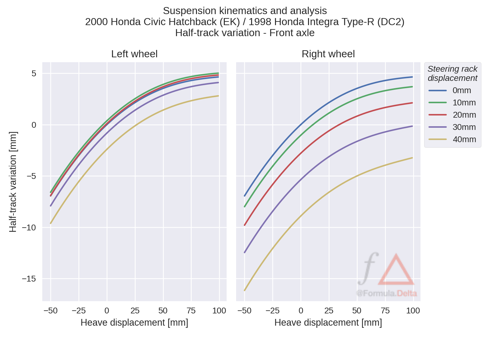
The half track variation in bump consistently increases, indicating that the kinematic roll center remains above the ground as the axle is articulated in heave.
The effect of the steering axis is also apparent, as the half track tends to decrease with large displacements of the steering rack, particularly for the right wheel. The left wheel initially experiences an increase in half track with steer, but this trend is reversed when the steering rack is displaced by 30mm.
Wheel centre recession
Wheel recession refers to the longitudinal movement of the wheel centre as the suspension moves in bump. This is measured directly from the kinematic simulation results. Wheel recession is desirable for ride and impact harshness.
The following figure shows the wheel centre recession as the system is articulated in bump during parallel wheel travel. A positive wheel recession value means that the wheel centre moved backwards from its nominal position.
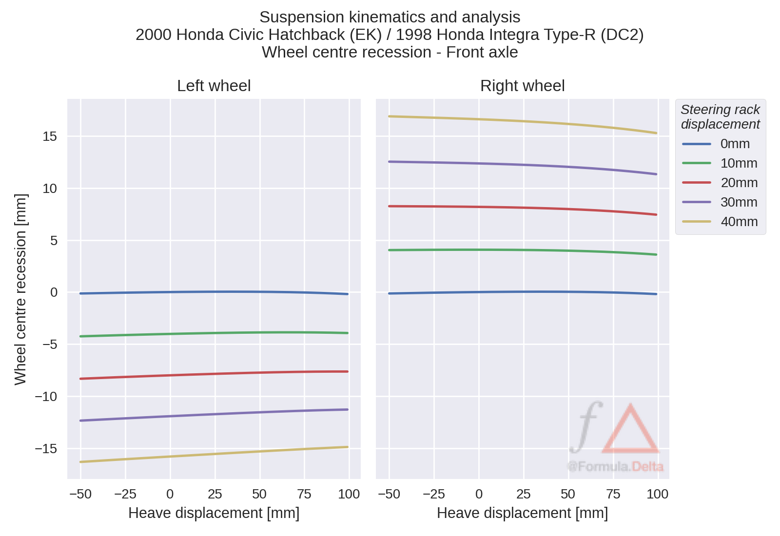
When the steering is on centre, there is minimal wheel centre recession in bump, indicating that kinematic wheel recession is not a design priority. The L-shaped lower control arm suggests that ride harshness is primarily managed using compliant wheel plane control techniques. This control arm design isolates the lateral force load path, allowing for decoupling of the longitudinal concerns from the lateral concerns. This allows for independent tuning of the handling and harshness characteristics through the bushings.
The steering-induced wheel recession is not as intuitive to comprehend. This effect is probably due to the toe variation that occurs in bump, as the wheel slightly rotates around the steering axis.
Toe variation
Toe variation refers to the change in toe angle as the wheel is articulated in bump. It is calculated by measuring the angle between the wheel plane as it intersects with the ground and the vehicle center plane.
Toe variation in bump is commonly known as bump steer, which creates a roll steer effect during cornering. Controlling the dynamic alignment of the vehicle is possible by controlling the toe variation characteristics. Roll steer, and by association, the bump steer, is often a consideration in an understeer budget calculation per the cornering compliance concept.
The toe variation in bump during parallel wheel travel is shown in the figure below. A positive toe angle indicates toe out and a negative toe angle indicates toe in.
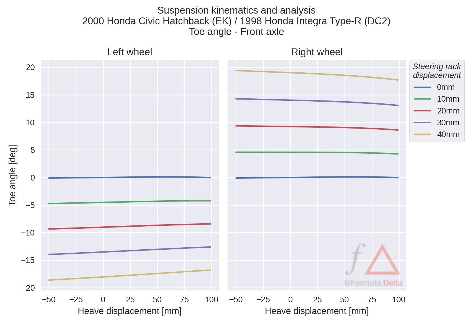
The on-centre toe variation remains nearly constant, changing less than ±0.2 degrees within the range of motion. Since steering is a control input, it is expected to have a toe offset with steer. Unlike the on-centre behavior, there is an observable amount of bump steer when the wheels are steered. This is an important aspect to consider as the dynamic alignment is ultimately what needs to be evaluated for vehicle setup.
Bump steer
To gain a deeper understanding into the toe variation behaviour of the front axle, we will study the bump steer characteristics in greater detail. Bump steer is the rate of toe variation in bump and is measured in units of degrees per metre. Bump steer is calculated by taking the derivative of the toe angle with respect to the bump displacement.
The figure below shows the bump steer characteristics for the vehicle under study. A positive value refers to a tendency to toe out with bump and a negative value refers to a tendency to toe in with bump.
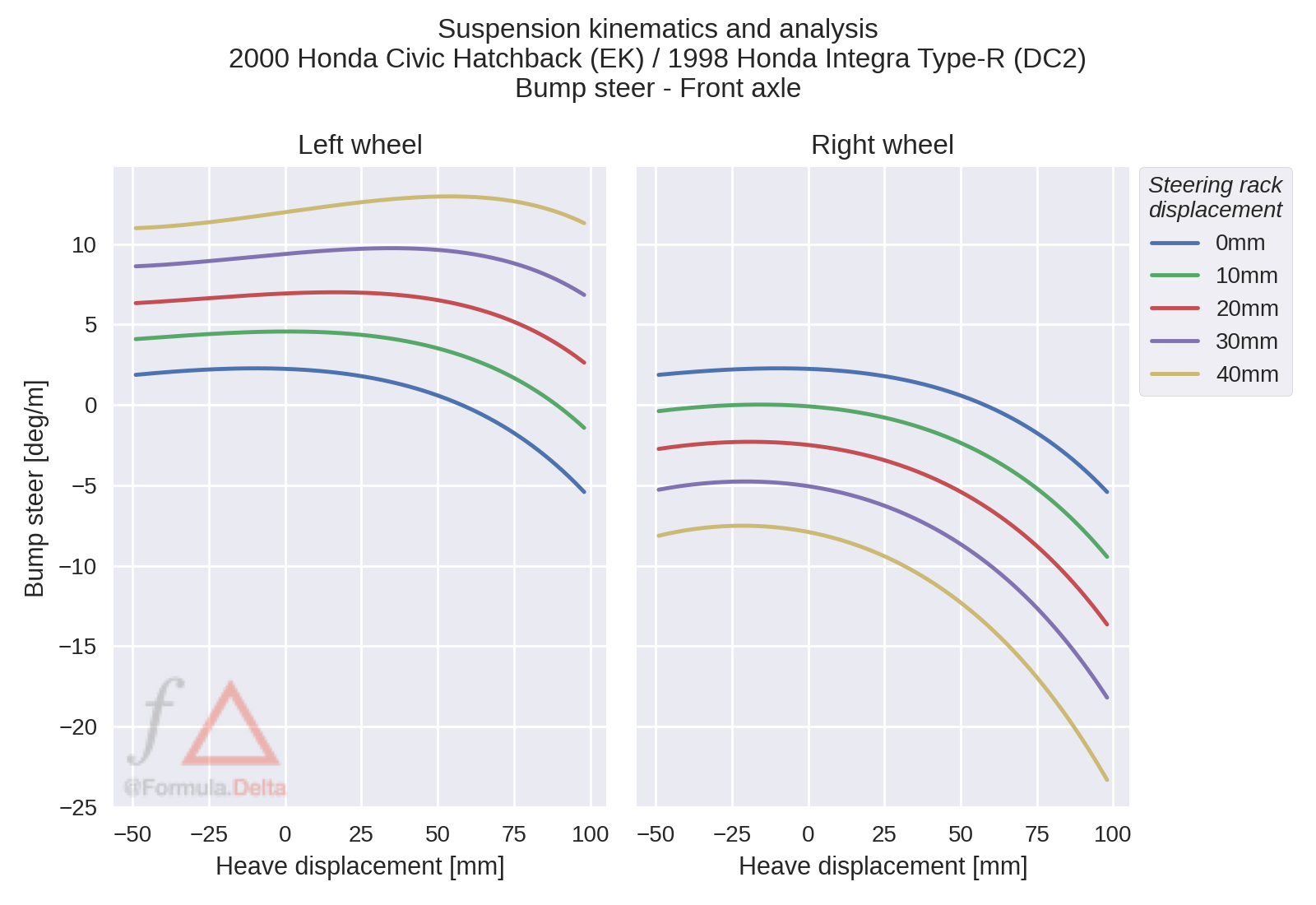
The on-centre bump steer at nominal ride height is 2.2 deg/m. This is relatively low by passenger car standards. Bump steer linearity is maintained up to a point where it quickly decreases and changes sign.
The severity of bump steer progressively increases with steering with the outside wheel tending to toe out with steer and the inner wheel tending to toe in with steer. The non-linearity of the right wheel at high bump displacement is not as interesting to observe as the wheel will likely be in droop during a corner.
Camber variation
Camber variation refers to the change in camber angle as the wheel is articulated in bump. This is measured by taking the angle between the wheel plane and the vehicle centre plane.
Camber variation modifies how the tire is presented to the road as the suspension articulates. It is an important consideration because the tire is sensitive to its inclination relative to the road. Camber compensation can be achieved through kinematics or static alignment.
The following figure shows the camber variation in bump during parallel wheel travel. A positive camber angle means that the top of the wheel leans outwards from the vehicle body. A negative camber angle means that the top of the wheel leans inwards towards the vehicle body.
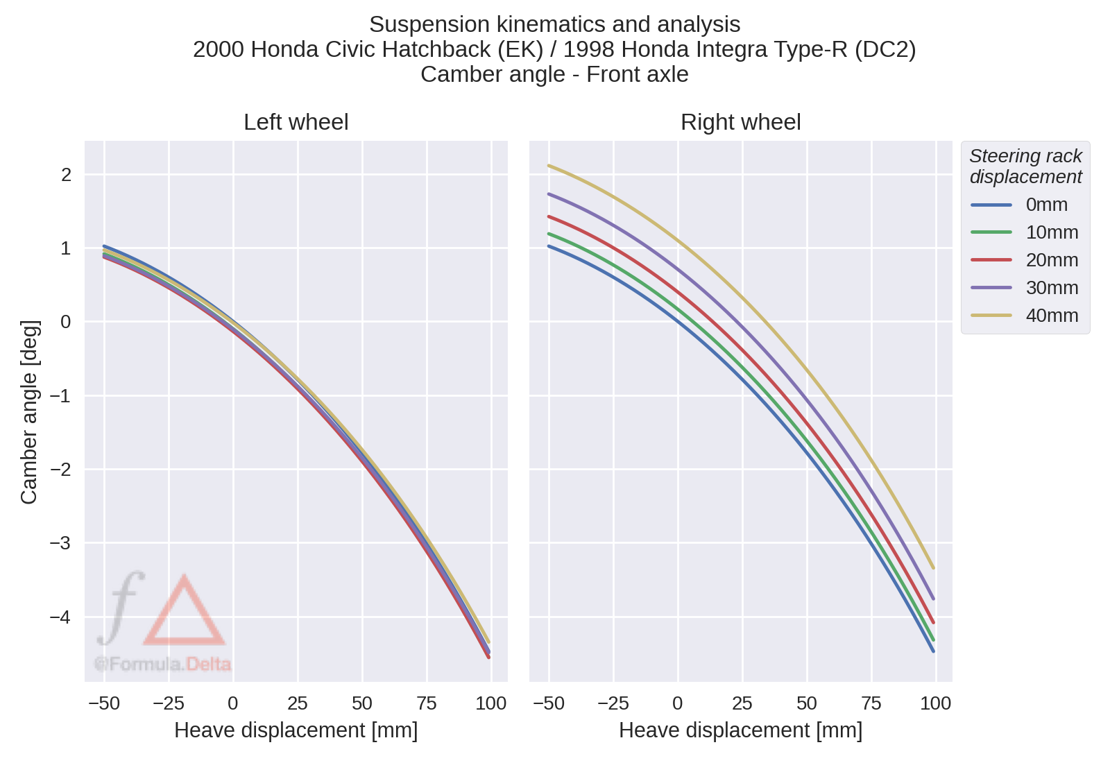
Camber angle tends to decrease as the suspension is articulated in bump. This trend accelerates as the suspension travels further. Steering effects are observed when comparing the camber curves of the left and right wheels. While the left wheel is relatively insensitive to steering rack displacement, the camber curve of the right wheel is shifted with each increment of the steering rack. This effect is due to the kingpin inclination angle, caster angle, and the direction of steer applied to each wheel.
Final comments
In this study, we analyzed the kinematic wheel plane control of a modified 2000 Honda Civic EK Hatchback front suspension. The double wishbone configuration of the front suspension common to golden-era Hondas show promising kinematic performance.
The analysis revealed several key findings, including the rising half track variation, minimal wheel center recession, and dynamic toe-out during combined bump and steer. The design of the lower control arm suggests that ride harshness is managed through elastokinematic techniques.
Kinematic wheel plane control is a foundational aspect of suspension analysis, and while we utilized computer simulations in this study, these metrics can also be measured experimentally. Understanding the suspension system’s working range is crucial in achieving your desired performance goals. Simple kinematic analysis, such as understanding the kinematic wheel plane control, can be a powerful tool in getting the performance out for your car. Such analysis provides the performance insights and development efficiencies that could be the competitive advantage that you need.
References
- Blundell, Michael, and Damian Harty. Multibody systems approach to vehicle dynamics. Elsevier, 2004.
- Dixon, John C. Tires, Suspension and Handling, Second Edition. Warrendale, PA: SAE International, 1996.
- O’Connell, Jay. “Design and Development of a New Suspension System for the Caterham SV-R,”