Steering kinematics of a Honda Civic EK Hatchback front suspension
Suspension designers spend a lot of effort on the steering system to get it just right. Not only is it one of the primary controls for maneuvering the vehicle, it is a source of feedback for the driver through the steering forces sent up the steering column.
While competition vehicle steering systems are designed to maximize the grip potential of the tires while relaying as much useful information to the driver, the Honda Civic EK and Honda Integra DC2 platforms are fundamentally economy car designs.
For those of us who want to use these platforms for competition purposes, we need to understand what this means. Our method of choice is to use simulation. Simulation provides us with repeatable, objective measures that we can use to evaluate the performance of the design.
Our discussion today focuses on the steering kinematics of a modified 2000 Honda Civic EK hatchback. We will look at the kinematic influences of steering on parameters such as toe and camber, as well as investigate the orientation of the steering axis which is a primary consideration in suspension design.
Acknowledgements
I would like to thank the following contributors for making this project possible.
-
Jay Thornton from Race3 Motorsport. After seeing one of our Instagram posts showcasing our preliminary effort in reverse engineering the front upright, Jay reached out to us and offered to 3D scan the part at his shop in Niagara Falls, ON. The resulting 3D scans proved to be invaluable for our reverse engineering efforts. We would not have been able to achieve the same level of success without Jay’s contributions. To learn more about Race3 Motorsports, please visit their website at www.race3.ca, or follow them on Facebook and Instagram at @race3_motorsports.
-
Ping Cheng Zhang from Formula Delta. Ping has been an instrumental part of this project from the start. Despite a busy time attack season, Ping took every opportunity to reverse-engineer parts of the EK20R. This involved diligently measuring physical components and ensuring that their digital representation were accurate. Through several rounds of discussion and collaboration, we were able to extract a useful set of suspension points, laying the foundation for a kinematic analysis of the front suspension of the Formula Delta EK20R.
Kinematic simulation
Suspension kinematics is the study of the geometry and motion of a vehicle’s suspension system, without consideration of forces. The motion of the suspension system can be modified to change how the tire is presented to the road. Consequently, this presents an opportunity for designers to change the design the of the suspension to tune the ride and handling characteristics of the vehicle.
Computer simulation is frequently used to analyze suspension kinematics since spatial mechanisms can be unintuitive to understand. To perform this analysis, a virtual model of the suspension system is created using a list of suspension coordinates. This model can then be articulated through its range of motion and analyzed. A visualization of the kinematic model is shown in the animation below.
This study uses the SolveSpace geometric constraint
engine as a kinematic solver, and makes use of
python-solvespace and slvstopy
to facilitate the simulation of the virtual model.
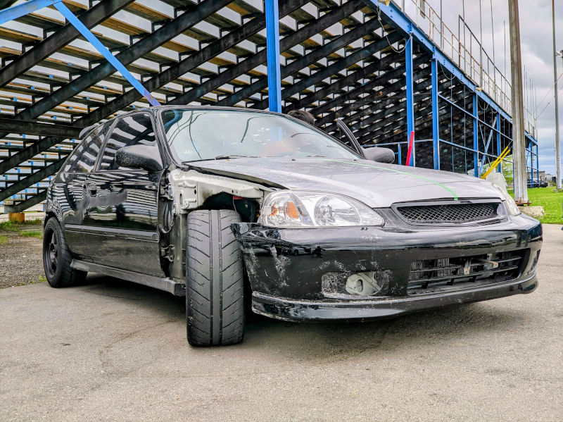
Vehicle under study

The kinematic model used in this study is based on the front suspension of a modified 2000 Honda Civic Hatchback (EK) using components from a 1998 Honda Integra (DC2), including the subframe, lower control arm, and upright. The upper control arm is assumed to be camber adjustable. Wheel fitment is 215/45R16 7Jx16 ET50 from a 1998 Honda Integra DC2 Type-R. To achieve zero static toe and zero static camber at nominal ride height, a virtual alignment is performed by adjusting the upper control arm and tie rod.
The purpose of this study is to evaluate the performance of the suspension system as designed from the factory. This provides a baseline assessment of the suspension system without aftermarket modification. Identifying the suspension system’s strengths and limitations can offer insights into the original design intent and its modification potential. This is crucial for achieving efficient performance outcomes from the vehicle development process.
It is important to note that every vehicle presents a unique scenario, and as such, we recommend using this analysis only as a reference for relative changes rather than an absolute guide. Correlational studies are a standard practice in the industry. and we encourage you to conduct your own before making any specific decisions around vehicle development.
Steering analysis
The lateral dynamics of a road vehicle are primarily controlled with the steering wheel. By directly manipulating the direction of the front tires, forces can develop at the axle which in turn can be used to direct the vehicle. This interaction between the steering system and how the wheel is oriented relative to the road influences vehicle dynamic performance.
The steering system also provides force feedback from the tires to the driver. The steering feeling can be adjusted by designing the steering geometry to produce desirable moments about the steering axis to complement the force & moment characteristics of the tire. Measurements like the scrub radius and mechanical trail are measured as part of kinematic study. The animation below highlights this phenomena, showing the tire contact patch at the intersection of the two lines and the steer axis intersection at the point in red.
In this study, the steering rack of the front suspension is displaced between -40mm and +40mm at successive ride heights. A positive displacement of the steering rack indicates movement to the left. Similarly, a positive steer angle, $\delta$, indicates that the wheels point to the left.
Rack to steer ratio
We begin with one of the most rudimentary of parameters to analyze. The steering ratio in this analysis is calculated as the derivative of the effective Ackermann steered angle with respect to the steering rack displacement. This is the kinematic contribution to the steering ratio. If the pinion diameter is known, an overall steering ratio can be approximated.
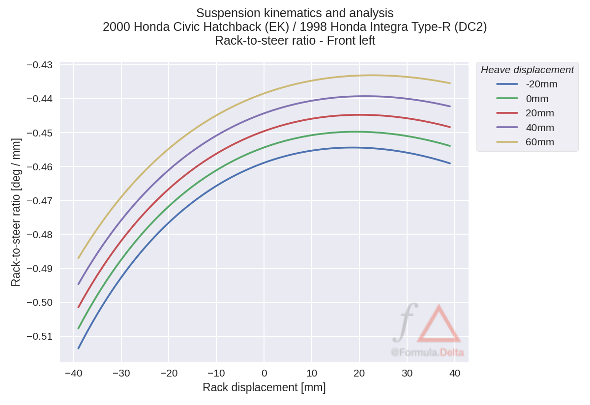
The negative ratio simply means that the wheels move to the right as the steering rack is displaced to the left. Given our choice of ISO coordinates and the rear-steer design of the car, this is expected.
At nominal ride height, the on-centre ratio is approximately -0.454 deg / mm. Ride height does not influence the trend. However, it does introduce an offset to the rack to steer ratio. A positive Ackermann steering effect is observable. As the rack moves to the right (ie. a negative rack displacement) the magnitude of the ratio increases. This is done mostly for low speed maneuverability in places like parking lots.
Dynamic toe offset
Another way we can understand the Ackermann steering geometry is by considering it as if it were a static alignment setting that changes with steer. We can analyze this effect by taking the difference between the left and right toe angles. Assuming that both left and right wheels are aligned to the same values, the dynamic toe as a result of the steering kinematics is the difference divided by two.
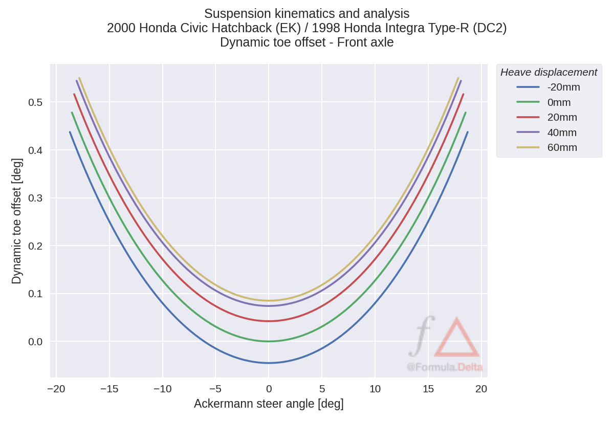
For ease of analysis, the x-axis has been changed to show the Ackermann steer angle. This is the effective steered angle of the front axle.
A positive dynamic toe offset means that the axle is aligned to be toe out. Here the Ackermann steering effect is apparent as the axle tends to toe out with steer. You can see the bump steer effect at the different ride heights though this effect is fairly small. We discussed this at length when we analyzed the kinematic wheel plane control.
Camber angle
While we have analyzed camber variation in the past, we can also investigate the influence of steering on this measurement. This effect is attributable to how the steering axis is positioned. Camber angle is measured by taking the angle between the wheel plane and the vehicle centre plane.
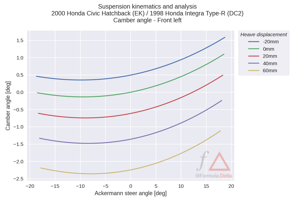
Lets clarify the sign convention to help us interpret this chart. In regards to the steering angle, a positive value indicates that the wheel is turning to the left. Given that we are analyzing the front left wheel of the car, this would mean that when the steering angle is positive we are considering the inside wheel during a left turn. In regards to the camber angle, a negative value means that the top of the wheel is leaning towards the vehicle centre plane.
There is a slight steering effect on camber with a nominal on-centre gain of 0.029 deg / deg, though the effect is not as powerful as the camber gain in heave. We can also observe a desirable effect whereby the outside wheel camber becomes more negative with steer and the inside wheel camber becomes more positive with steer.
Caster angle
In our first look into the steering axis orientation, we will begin by investigating the caster angle. The caster angle is the lean angle of the steering axis in side view. This is often an important consideration for on-centre steering feeling.
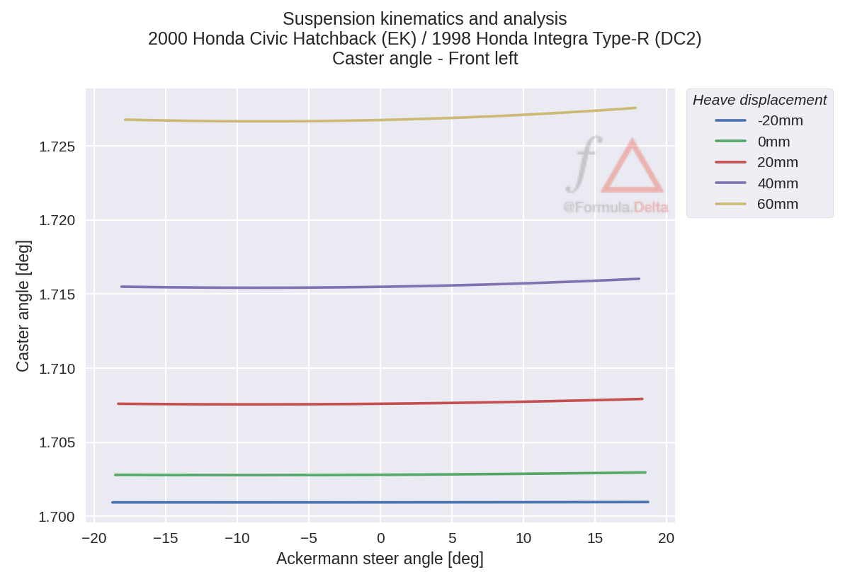
The caster angle is practically constant throughout the range of motion, even in bump. You can expect the caster angle to be approximately 1.7 deg at nominal ride height.
Kingpin inclination angle
Moving on to the front view, the kingpin inclination angle (KPI) is the lean angle of the steering axis in front view. Just like the caster angle, this is an important consideration for on-centre steering feeling. For performance purposes, we generally want to limit the amount of KPI introduced into the design as doing so produces positive camber with steer.
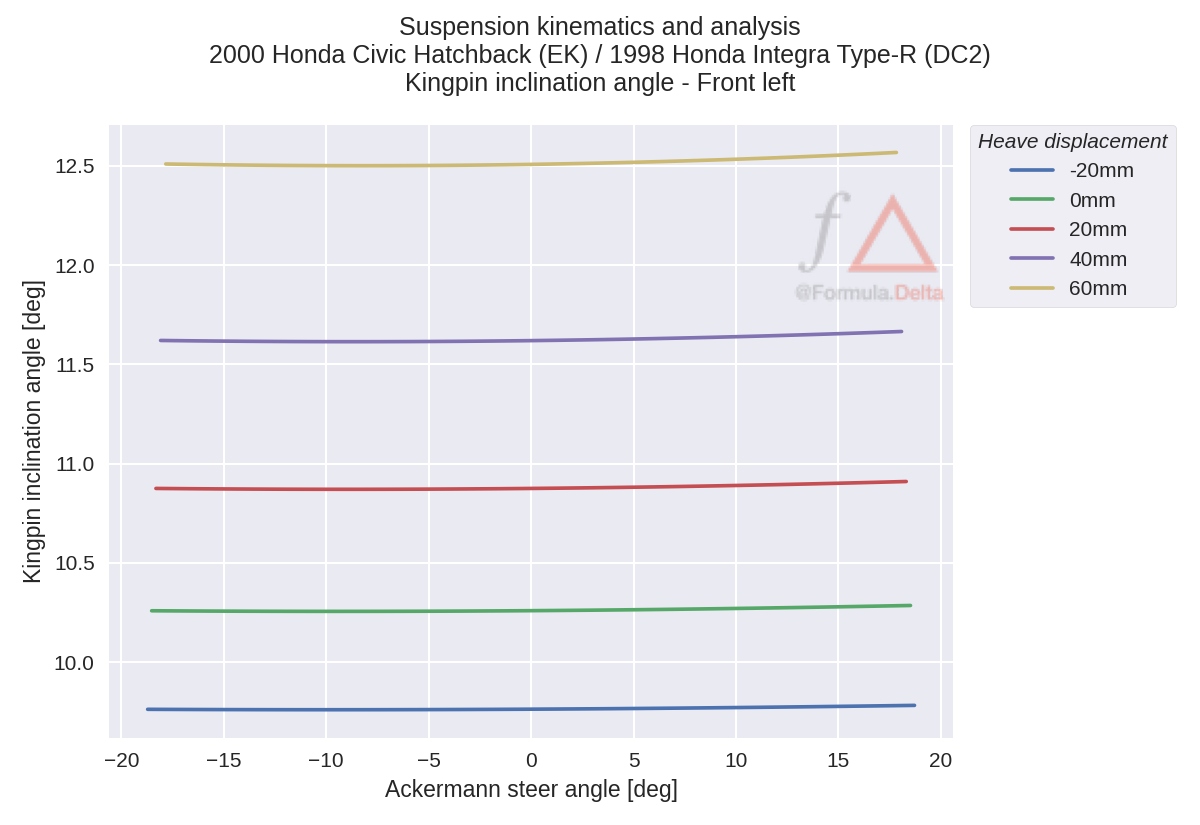
KPI is practically constant through the steering range. However, we do see that ride height does have some influence by introducing an offset. This is unsurprising given the short-long arm double-wishbone design of this chassis. This just means that the upper arm is moving inwards with heave faster than the lower control arm.
Mechanical trail
Our last two metrics investigate how the steering axis interacts with the road plane. The location of this intersection has a strong influence on the steering feedback produced. This is because it acts as a moment arm between the tire contact patch and steering axis.
Mechanical trail is the longitudinal distance from the steer axis intersection and the tire contact patch. This is the moment arm* that produces a torque about the steering axis in response to a lateral tire force. The mechanical trail is measured in a reference frame that rotates with the tire.
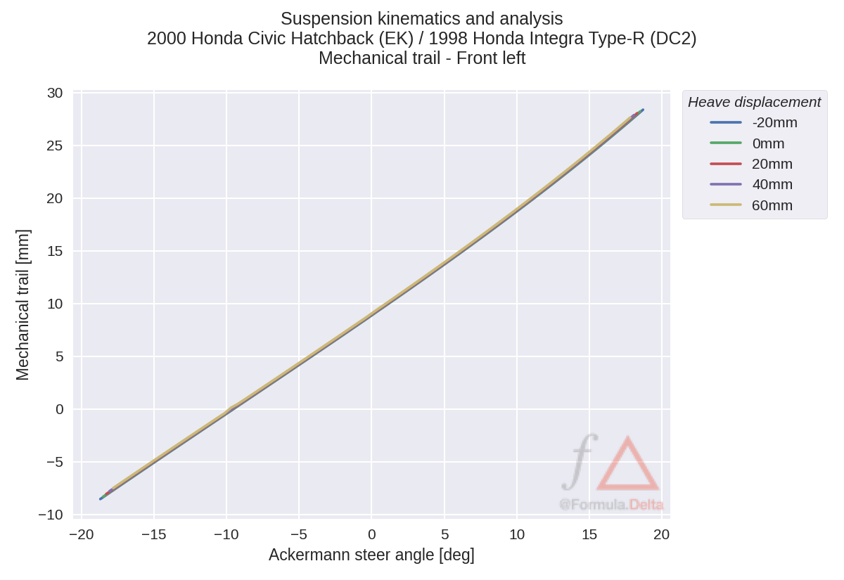
The mechanical trail linearly increases as the wheel is turned to the left and is completely insensitive to ride height. Recall that since we are analyzing the front left wheel, this means that during a turn the mechanical trail will decrease for the outside wheel and increase for the inside wheel. Interestingly, the mechanical trail changes sign at the end of its steering range.
The animation at the beginning of our analysis can reveal details about why this is happening. We know that the steer axis is practically constant throughout the steer range. However, if you watch closely, you will see the contact patch move forward and backwards relative to steer axis intersection.
The nominal on-centre mechanical trail of approximately 9.0 mm. Based on existing literature, this is on the low end of the spectrum. This is unsurprising due to the economy car origins of the Honda Civic.
*Aside: For simplicity, the classical definition is used. While it is technically incorrect, it is followed for ease of understanding.
Scrub radius
The scrub radius is the lateral distance from the steer axis intersection and the tire contact patch. This is the moment arm* that produces a torque about the steering axis in response to a longitudinal force. The scrub radius is measured in a reference frame that rotates with the tire.
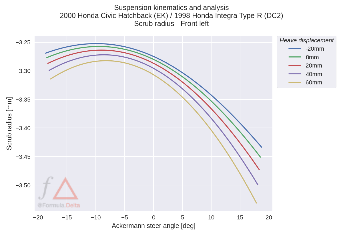
In typical fashion for a front-wheel drive car, we see a small negative scrub radius through the range of travel. At nominal ride height, the on centre scrub radius is approximately -3.28 mm. While the graph shows some variation with steer, it is important to observe the scale of the y-axis. The scrub radius only changes a couple tenths of a millimetre in the range of motion.
Just as a reminder, we are analyzing the car with 215/45R16 ET50 wheel fitment. This metric will change with different wheel fitments and camber alignments. The key takeaway here is that from the factory the car ships with a small amount of negative scrub and that larger wheel fitments with low offset rims will likely cause the sign to change.
Highlights
While the Honda Civic EK and Honda Integra DC2 platforms are famed for their double-wishbone front suspension, they are still economy cars at their core. There are plenty of modifications you can make to improve its handling performance. However, deciphering what actually works is the challenge. It is also the fun part of doing your own build.
We are going to try something new for this installment. In this section, I will highlight what I believe are the key features of the design and note areas of development that could be interesting to implement. My discussion here will be limited to what I have observed in the kinematic simulation, so you will have to work with a vendor or supplier to figure out what actually works.
- The combination of bump steer, pro-Ackermann steering and compliance effects will probably result in dynamic toe out during combined brake / cornering. Most discussions default to recommending static toe out during alignment despite dynamic adjustment already tending to toe out. This leaves static toe in on the front axle an unexplored option as the inner tire may not be operating within its peak operating window assuming certain tire load sensitivity characteristics. This is an opportunity for investigation, both in simulation and in testing.
- There is very little mechanical trail designed into the platform due to the low caster angle of the steer axis. This is a neat feature if you retain with stock wheel fitment since it allows the steering feedback to be primarily derived from the tire self aligning torque. However, modern steering sensibilities have been trending towards higher caster angles. This can be observed by looking at the front suspension of a 10th generation Honda Civic or first generation BRZ / FRS - the strut is clearly canted backwards much more than vehicles of this generation. Given this, caster adjustable upper control arms seem like a reasonable modification. While there are some desirable kinematic effects with additional caster, I would suggest this primarily as a ergonomic mod to improve steering feel. However, this may not be meaningful depending on your wheel fitment.
- Typical for a front wheel drive vehicle is the slight negative scrub on stock wheels. Big wheel fitments with low offsets will increase the scrub radius from stock. It can be assumed that you will have positive scrub as you reduce the rim offset. For example, fitting a 255/40R17 tire with a +35 mm offset rim and 3 mm spacer would net you scrub radius in excess of 35 mm. This is going to be the dominating effect in the steering feel, regardless of if you add an additional degree of caster via an adjustable upper control arm. Compensating for this would require a new knuckle design.
Conclusion
In this study, we investigated the kinematic behaviour of a modified 2000 Honda Civic EK Hatchback front steering system. While the double-wishbone design is advantageous for those using the EK / DC2 platform for competition use, the design is tailored for more leisurely pursuits such as going to the grocery store.
Caster adjustment kits are a reasonable modification to make given the design. However, steering feel will probably be dominated by scrub effects as soon you reduce the wheel offset. Perhaps with power steering it could make a difference, but it seems unlikely it would have significant performance benefit considering the range of adjustment on most aftermarket kits. We may have to just settle for grocery-getter steering kinematics and deal with the scrub radius induced torque steer on low offset wheels.
References
- Milliken, William F., and Douglas L. Milliken. Race car vehicle dynamics. Vol. 400. Warrendale: Society of Automotive Engineers, 1995.
- Blundell, Michael, and Damian Harty. Multibody systems approach to vehicle dynamics. Elsevier, 2004.
- Veneri, M., and M. Massaro. “The effect of Ackermann steering on the performance of race cars.” Vehicle system dynamics 59, no. 6 (2021): 907-927.
- O’Connell, Jay. “Design and Development of a New Suspension System for the Caterham SV-R,”