Kinematic curves of the Acura RSX front suspension
This article is part of a series on the kinematic simulation and analysis of the Acura RSX suspension. To learn more, feel free to check my other posts:
Front Suspension
- Analysis of the Acura RSX front suspension geometry
- You are here! - Kinematic curves of the Acura RSX front suspension
- Motion ratio curves of the Acura RSX front suspension
- Kinematic roll centre analysis of the Acura RSX front suspension
Rear Suspension
- Kinematic curves of the Acura RSX rear suspension
- Motion ratio curves of the Acura RSX rear suspension
- Kinematic roll centre analysis of the Acura RSX rear suspension
Full Vehicle
Understanding how the wheel moves relative to the chassis is important because it affects the tire movement relative to the ground. Suspension geometry is carefully designed to control this motion in a desirable way. Because the tire is sensitive to slip and inclination, wheel movement affects tire operation which in turn affects vehicle handling.
Using kinematic simulation, we can study the wheel plane motion and understand how the tire is being controlled. In this article, we analyze the front suspension of an Acura RSX to understand the wheel plane motion as it is articulated in bump and steer.
Kinematic simulation
Kinematic simulation is an analysis tool that predicts the wheel motion by virtually displacing it in bump and steer. This is done by entering the suspension coordinates into a kinematics solver.
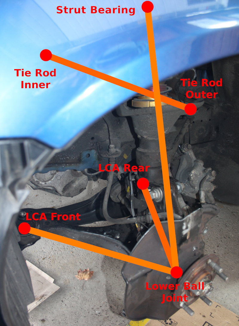
Suspension coordinates are not typically made available for road cars and require measurements from the car. The suspension coordinates used in this study are obtained by our own testing. The image below shows the front suspension geometry of the Acura RSX.
In this study, we use the kinematic simulation to articulate a quarter car model. From the simulation output, we can study the wheel plane motion to investigate how well the tire is being controlled. The motions are visualized below.
Coordinates are referenced using the ISO vehicle coordinate system. For clarity, the sign convention is listed below:
- \(+X\) is forward
- \(+Y\) is to the left
- \(+Z\) is up
- \(+\delta\) is steering to the left
Half track variation
The half track variation is lateral displacement of the tire contact patch. Because the slip angle is the arctangent of the contact patch velocity components, half track variation results in a lateral velocity at the contact patch therefore causing tire slip.
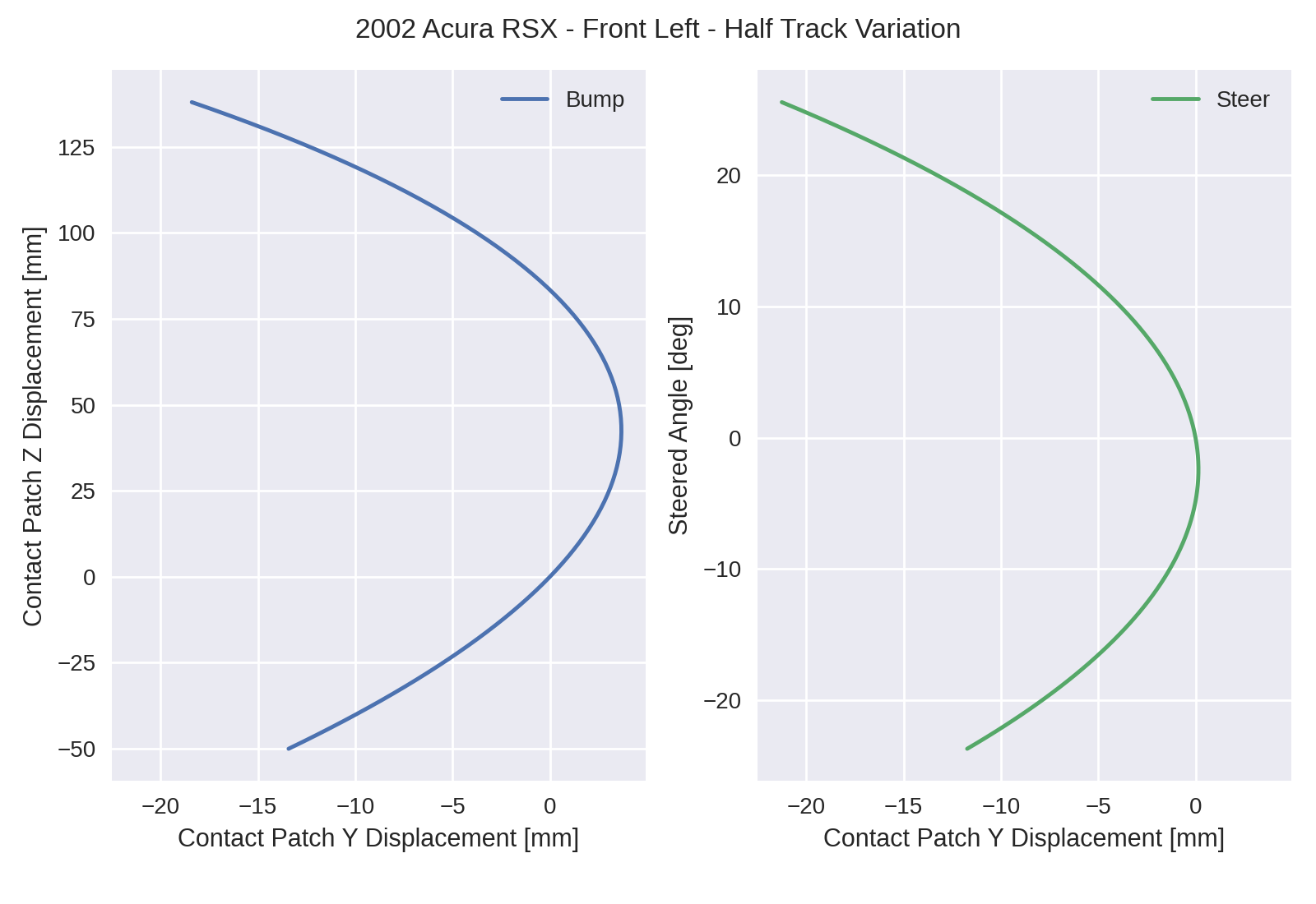
In both bump and steer, there are regions where the half track displacement is positive. In bump, that region is between +0mm and +83mm. In steer, that region is between -4deg and +0deg. You can expect the half track to vary from anywhere from -20mm to +4mm as the suspension is articulated.
Camber variation
Tires are sensitive to inclination angle. In other words, the tire is sensitive to the lean angle relative to the road. The camber variation helps control the tire inclination angle as the chassis is in roll.
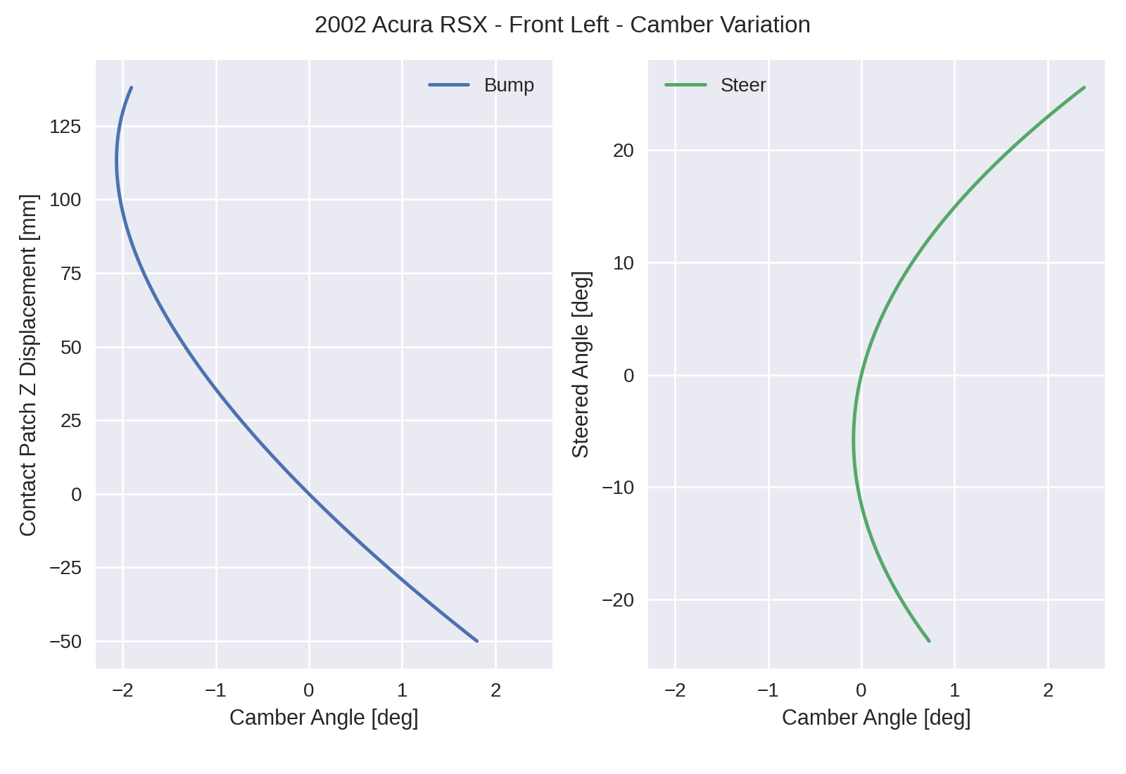
The suspension exhibits diminishing negative camber gain in bump. Near the end of the suspension travel at +114mm of bump, the suspension reaches maximum camber. There is some negative camber gained between +0deg and +12deg of steering; however, this amount is small in comparison to the positive camber gained outside this region. This is likely because of the large kingpin inclination angle and small caster angle built into the RSX front suspension geometry.
Toe variation
The change in toe angle with bump is the toe variation, also known as bump steer. When looking at the axle as a whole, the combined toe variation of each wheel results in roll steer. Toe variation is depicted with steered angle to match the sign convention used in other graphs. The steering graph is omitted because the steering directly changes the front toe angle.
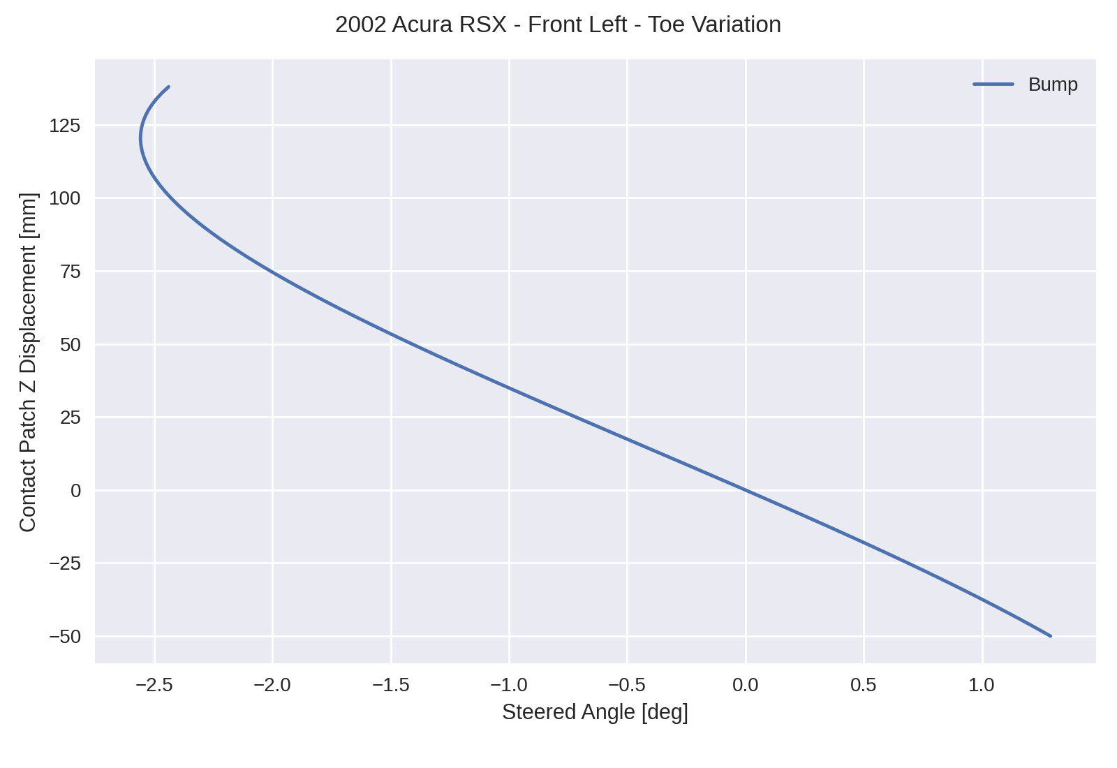
The wheel plane tends to toe-in with bump for most of the suspension travel. At +122mm of bump, maximum toe-in is achieved and the steered angle begins to increase. This happens near the end of the suspension travel where the wheel plane already has substantial toe-in at -2.6deg.
Final comments
There are many interesting properties of the McPherson strut design on the Acura RSX front suspension. The wheel plane control is intriguing near the end of its suspension travel. Because cars are commonly modified and lowered for track use, this represents a challenge for vehicle setup and tuning.
Kinematic simulation is a powerful tool for understanding the effects of the suspension geometry. In this analysis, we looked at wheel plane control as the initial building block of our understanding. While wheel plane control is a foundational part of kinematic analysis, there is much more that numerical simulation can do to aid in vehicle setup.
Acknowledgements
I would like to acknowledge Ping Zhang at Formula Delta for obtaining and sharing the suspension points for this study.
References
- Milliken, William F., and Douglas L. Milliken. Race car vehicle dynamics. Vol. 400. Warrendale: Society of Automotive Engineers, 1995.
- Blundell, Michael, and Damian Harty. Multibody systems approach to vehicle dynamics. Elsevier, 2004.