Anti-lift, anti-dive and kinematic pitch centre analysis of the Acura RSX suspension
This article is part of a series on the kinematic simulation and analysis of the Acura RSX suspension. To learn more, feel free to check my other posts:
Front Suspension
- Analysis of the Acura RSX front suspension geometry
- Kinematic curves of the Acura RSX front suspension
- Motion ratio curves of the Acura RSX front suspension
- Kinematic roll centre analysis of the Acura RSX front suspension
Rear Suspension
- Kinematic curves of the Acura RSX rear suspension
- Motion ratio curves of the Acura RSX rear suspension
- Kinematic roll centre analysis of the Acura RSX rear suspension
Full Vehicle
Vehicle chassis systems work together to react handling loads in a desirable way. The relationship between the front and rear axles become clear when analyzing the side-view geometry. Four wheel braking is a full vehicle event, meaning the load paths from both front and rear axles must be considered to understand the longitudinal dynamics.
To gain an appreciation of these interactions, we will analyze the side-view suspension geometry of the Acura RSX. The definition of anti-lift and anti-dive geometry is discussed, and the existence of a pitch centre is explored.
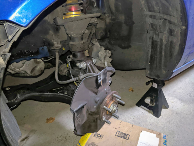
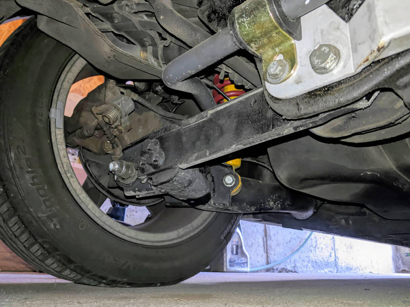
Suspension design
The Acura RSX features a MacPherson strut front suspension and a H-arm with camber link rear suspension. The MacPherson strut front suspension consists of a lower control arm and a strut assembly, both of which locate the side-view kinematic instant centre. For the rear suspension, the H-arm formed by the lower control arm reacts the longitudinal forces exclusively. The Acura RSX suspension system is shown below with the front and rear designs on the left and right respectively.
Using computer simulation, a kinematic model of the Acura RSX is created in a virtual environment where the linkages can be articulated through its range of motion. The assembled virtual vehicle is shown below.
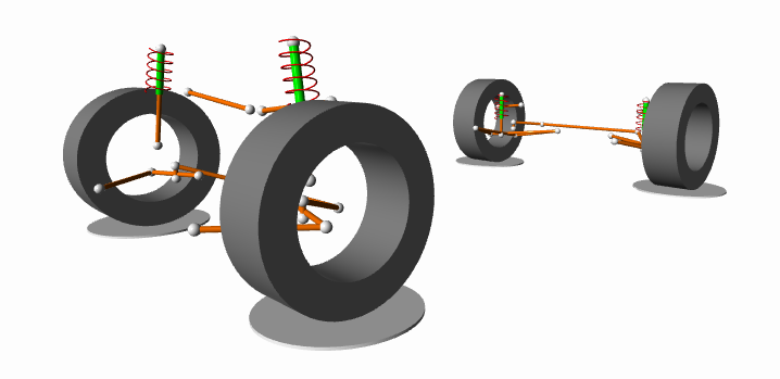
The kinematic simulation used in this study is self-developed using free and open source software frameworks.
Kinematic pitch centre and anti geometry
Similar to how we discussed the front kinematic roll centre and rear kinematic roll centre, the same concepts can be applied for the longitudinal dynamics. The kinematic pitch centre is a virtual point on the side plane where longitudinal forces can be resolved into the suspended mass.
The side-view kinematic instant centre is determined differently for the front and rear wheels because they have different suspension architectures.
The side-view kinematic instant centre for the MacPherson strut front suspension is found at the intersection of:
- the lower control arm plane defined by the two inboard attachment points and the outer ball joint
- the upper strut plane defined by the upper strut attachment point and a normal vector defined by the strut
- the side-view plane defined by the front and rear tire contact patches
The side-view kinematic instant centre for the H-arm with camber link rear suspension is found at the intersection of:
- the line defined by the two inboard attachment points of the lower control arm
- the side-view plane defined by the front and rear tire contact patches
Under braking, the side-view virtual swing axle is formed by drawing a line from the tire contact patch to its respective side-view kinematic instant centre. The intersection of the front and rear side-view virtual swing axles is the kinematic pitch centre.
The use of antis in kinematic analysis is convenient because it handles asymmetries in the suspension geometry and in the forces applied at each wheel. Because there are many types of antis, we will discuss them in the analysis.
Analysis
The analysis will focus on what happens in heave. In this motion, all four wheels are displaced the same amount and in the same direction. This is representative of what would happen when the vehicle is lowered.
Based on published data for the Acura RSX by the National Highway Traffic Safety Administration, the following values are used for the weight distribution and the centre of gravity height:
- Vehicle fore/aft weight distribution \(\text{WD} = 61/39\;[\%]\)
- Centre of gravity height above the ground \(h = 533\;\text{[mm]}\)
Front anti-lift
Front anti-lift refers to the ability of the front suspension to react the front longitudinal load transfer induced by the drive force. In a typical front wheel drive layout, the drive force acts at the wheel centre and through the side-view kinematic instant centre. The percentage of front anti-lift is given by the following equation:
\[\%\:\text{anti-lift}_{front} = \frac{l}{h} \tan{\theta} \times 100\]Where:
- \(l\) is the vehicle wheelbase [mm]
- \(h\) is the height of the centre of gravity above the ground [mm]
- \(\theta\) is the angle of a line originating at the wheel centre going through the side view kinematic instant centre relative to the road plane [rad]
Depending on the angle of the side-view line of action, the front geometry can have either anti-lift or pro-lift. For the Acura RSX, the side-view line of action momentarily goes below the horizontal meaning that the front suspension will briefly provide pro-lift geometry at the end of its droop travel.

Our findings of pro-lift at the end of the droop travel is confirmed in the data with the anti-lift angle crossing zero with just 37 mm of droop travel. At factory ride height, you can expect an anti-lift angle of around 1.0 deg which equates to 8.8% front anti-lift.
Front anti-dive
Front anti-dive refers to the ability of the front suspension to react the front longitudinal load transfer induced by the front braking force. In a vehicle with outboard brakes, the braking force acts at the tire contact patch and through the side-view kinematic instant centre. The percentage of front anti-dive is given by the following equation:
\[\%\:\text{anti-dive}_{front} = \%\:\text{braking}_{front} \frac{l}{h} \tan{\theta_{front}}\]Where:
- \(\%\:\text{braking}_{front}\) is the brake force contribution of the front axle [%]
- \(\theta_{front}\) is the angle of a line originating at the tire contact patch going through the side view kinematic instant centre relative to the road plane [rad]
The percentage of front braking force is in consideration of the anti effect for the forces generated by front axle exclusively. As an aside, you will notice the anti-lift calculation is just a special case of this equation where 100% of the drive force is allocated to the front axle.
Because we do not know the percentage of front braking force, we can not compute the percentage anti-dive. However, we can calculate the anti-dive ratio before considering the percentage brake force. This value is calculated as:
\[\text{anti-dive ratio}_{front} = \frac{l}{h} \tan{\theta_{front}}\]The graph below shows the computed front anti-dive angle and front anti-dive ratio as the wheels are displaced in heave.

Due to the fixed upper strut plane on a MacPherson strut, the side view kinematic instant centre is mainly located by the lower control arm. Keen observers will notice that the inboard lower control arm suspension points are slightly angled, so some anti effect is expected. At factory ride height, you can expect the front anti-dive angle to be approximately 2.7 deg with an front anti-dive ratio of 0.23.
Rear anti-lift
Rear anti-lift refers to the ability of the rear suspension to react the rear longitudinal load transfer induced by the rear braking force. In a vehicle with outboard brakes, the braking force acts at the tire contact patch and through the side-view kinematic instant centre. The percentage of rear anti-lift is given by the following equation:
\[\%\:\text{anti-lift}_{rear} = \%\:\text{braking}_{rear} \frac{l}{h} \tan{\theta_{rear}}\]Where:
- \(\%\:\text{braking}_{rear}\) is the brake force contribution of the rear axle [%]
- \(\theta_{rear}\) is the angle of a line originating at the tire contact patch going through the side view kinematic instant centre relative to the road plane [rad]
Just like in the front anti-dive case, we do not know the percentage of rear braking force for the Acura RSX. Therefore, we calculate an anti-lift ratio as a substitute to see how the rear anti-lift evolves through the suspension travel.
\[\text{anti-lift ratio}_{rear} = \frac{l}{h} \tan{\theta_{rear}}\]The graph below shows the trend of the rear anti-lift angle and the rear anti-lift ratio through the heave travel.

Because of the rear suspension architecture, the side-view kinematic instant centre for does not move much relative to the suspended mass. The side-view swing axle is also much shorter as compared to the front suspension, resulting in large anti-lift angles. Recall that percentage anti-lift takes into consideration the percentage of rear braking force, so the effective percentage of rear anti-lift is likely much less. At factory ride height, you can expect a rear anti-lift angle of 22 deg and rear anti-lift ratio of 1.96.
Kinematic pitch centre
The kinematic pitch centre is the longitudinal equivalent of the kinematic roll centre. It is a virtual point in which longitudinal forces can be resolved into the suspended mass. This is possible because the braking forces can be translated along their respective line of action per the Principle of Transmissibility.
For the Acura RSX, the side-view geometry is not symmetrical. Additionally, it is unlikely that the magnitude of forces acting at the front and rear wheels are the same because of the brake bias. Consequently, jacking forces must be considered in a force analysis of the suspended mass. Further distinction can be made since we are making assumptions about how forces are reacted into the suspended mass using kinematic constructs.
For this analysis, we will study the vertical and longitudinal moment arms around the vehicle centre of gravity from the pitch centre.

The pitch centre at factory ride hight creates a vertical moment arm 425 mm in length and a longitudinal moment arm of 1306 mm. As the vehicle is lowered, both the vertical and longitudinal moment arms decrease in length. This suggests the platform becomes less sensitive to longitudinal braking and jacking forces as the ride height is reduced. However, a force analysis is required to confirm this statement.
Final comments
Longitudinal dynamics are an important consideration. Braking is a regular occurrence on any road course and is important because it precedes corner entry. Those with large aerodynamic packages must recognize that its effectiveness is contingent on the ability to control the platform.
In this analysis, we looked at some of the fundamental suspension parameters influencing the longitudinal dynamics. We learned how antis are designed on a road car and how the choice of front and rear suspension architecture will influence the location of the side-view kinematic instant centre. This reinforces how complex chassis design is and highlights the need for a systematic approach to vehicle setup.
Acknowledgements
This work is made possible with help from Ping Zhang at Formula Delta who shared the suspension points for the Acura RSX. You can learn more about Ping and his time attack project on his website, Facebook or Instagram.
References
- Milliken, William F., and Douglas L. Milliken. Race car vehicle dynamics. Vol. 400. Warrendale: Society of Automotive Engineers, 1995.
- Walz, Marie C. Trends in the static stability factor of passenger cars, light trucks, and vans. No. HS-809 868. 2005.