Motion ratio curves of the Acura RSX front suspension
This article is part of a series on the kinematic simulation and analysis of the Acura RSX suspension. To learn more, feel free to check my other posts:
Front Suspension
- Analysis of the Acura RSX front suspension geometry
- Kinematic curves of the Acura RSX front suspension
- You are here! - Motion ratio curves of the Acura RSX front suspension
- Kinematic roll centre analysis of the Acura RSX front suspension
Rear Suspension
- Kinematic curves of the Acura RSX rear suspension
- Motion ratio curves of the Acura RSX rear suspension
- Kinematic roll centre analysis of the Acura RSX rear suspension
Full Vehicle
Introduction
Before the concept of vehicle suspension, passengers had to endure an uncomfortable ride as they felt every bump in the road. Technology has advanced since the age of horse-drawn coaches. Today, we have sophisticated multi-link suspension designed not just for passenger comfort, but carefully designed to react handling loads.
The motion ratio is the displacement ratio of one element to another. This ratio is important when considering resistive mechanical elements because it represents the mechanical advantage (or disadvantage) it has from a certain location. This means the spring rate you install on your car is not necessarily the effective spring rate at the wheel.
To demonstrate this concept, we will analyze the Acura RSX front suspension and compute the motion ratios using kinematic simulation.
Motion ratios
Because there are different ways of defining the motion ratio, it is important to have the same understanding to prevent confusion. In this article, we are defining the motion ratio as the ratio between the displacement of a mechanical element relative to the vertical displacement of the wheel centre; or:
\[{MR} = \frac{dx_{elem}}{dx_{wc,z}}\]Where:
- \(dx\_{elem}\) is the change in the element length
- \(dx\_{wc,z}\) is the change in the wheel centre vertical position
The change in the element length is computed from a kinematic simulation using a second-order central difference.
On the Acura RSX front suspension, there are three motion ratios of interest:
- the spring displacement
- the damper displacement
- the anti-roll bar twist angle
In addition to the spring and damper elements, the steering degree of freedom can be articulated to add another ratio to our list:
- the rack displacement to road wheel angle ratio
This brings the list to four motion ratios. We will use the ISO vehicle coordinate system to describe the vehicle frame of reference.
Springs
The spring motion ratio is the ratio between the spring length and the wheel centre vertical displacement.
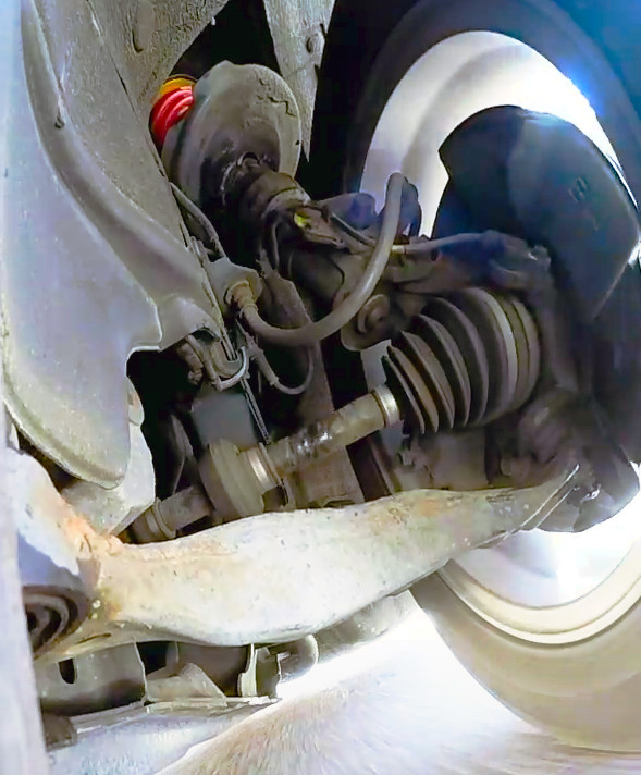
The MacPherson strut front suspension on the Acura RSX uses a coil spring that is offset from the strut axis. Manufacturers do this to reduce bending loads in the strut. We assume that the coil spring is collinear with the steering axis as an approximation of the line of action.
Dampers
The damper motion ratio is the ratio between the damper length and the wheel centre vertical displacement.
Because the damper is engaged on a different line of action than the spring, the damper needs to be studied separately. On the Acura RSX, the damper axis is slightly offset from the steering axis, likely for packaging reasons. This is the ratio of interest if you have a coil over kit installed on your car.
Anti-roll bar
In this analysis, we define the anti-roll bar motion ratio as the ratio between the angular displacement of the lever arm (ie. the bar twist angle) and the wheel centre vertical displacement.
The anti-roll bar motion ratio is a useful quantity to know when setting up a vehicle. Anti-roll bars are unique because they do not affect the stiffness in pitch and heave. The Acura RSX uses a control arm mounted end link to actuate the anti-roll bar lever arm. The torsional stiffness of the bar provides resistance as it is twisted. There are several ways to define the anti-roll bar motion ratio. Use the correct definition for your calculations!
Steering
Although not a resistive mechanical element, the steering rack to road wheel angle is still an important property to know. The steering ratio is typically quoted as a singular value; however, the steering ratio is best described by a curve.
The steering ratio in this analysis is defined as the ratio between the road wheel angle and the steering rack displacement. This motion is visualized below:
Analysis
With the strut being the primary component reacting handling loads, we will start with the motion ratios of the spring and damper.

A unique property of the MacPherson strut design is the near unity motion ratio. Because the strut is attached to the knuckle, it must displace a similar amount. The damper motion ratio is slightly lower than the spring motion ratio; however, this is expected because they are on different lines of action.
Moving to the next resistive element, we can study the anti-roll bar motion ratio. The motion ratio is no longer dimensionless because it is between an angular and linear quantity.

The anti-roll bar motion ratio varies slightly near nominal ride height. Beyond +25 mm of bump the motion ratio steadily decreases up to the end of the suspension travel.
Lastly, we have the steering motion ratio represented by the rack to road wheel angle ratio. In this scenario, a positive rack displacement causes the tires to steer to right.

It is apparent that the steering ratio is not constant left to right. Given that the steering ratio increases as the front left wheel steers to the left, this would indicate pro-Ackermann steering.
Final Comments
Knowing the motion ratios of your car is critical for proper vehicle setup. We found the Acura RSX front suspension has near unity spring and damper motion ratios. We also characterized the sway bar twist motion ratio. These values can be be used in a roll stiffness worksheet to quantify the effects of spring rate on handling.
The use of kinematic simulation allows the suspension to be analyzed in ways not possible in a typical garage. Simulation allows you to analyze a design without the cost and time investment of physically testing for all parameters. With some ingenuity and effort, these tools need not be out of reach.
With automotive manufacturers designing more sophisticated suspension systems, understanding how the design works is becoming increasingly difficult. Looking at the fundamentals can reveal the trade-offs that were made for comfort and performance, a first step to any vehicle development project!
Acknowledgements
I would like to acknowledge Ping Zhang at Formula Delta for sharing the suspension points used in this study.
References
- Milliken, William F., and Douglas L. Milliken. Race car vehicle dynamics. Vol. 400. Warrendale: Society of Automotive Engineers, 1995.
- Blundell, Michael, and Damian Harty. Multibody systems approach to vehicle dynamics. Elsevier, 2004.